


By Steve Moss and Carly Rixham January 21, 2026
© Bing-Jhen Hong
For many people who care about solar energy, caring for the environment is just as important. Trees are a big part of what makes our surroundings feel natural and beautiful. Cutting down a tree to install a solar array might feel a bit defeating.
Knowing the optimal location for installing a solar array increases annual generation by several percentage points if shade from nearby structures and trees is minimized, if not eliminated. Knowing how much energy is lost to shade helps homeowners decide whether to keep a tree or structure, trim it, or remove it. In general, it comes down to minimizing losses with nominal, if any, tree removal. In addition, by knowing the cost of leaving a tree in place (lost generation) homeowners or solar developers can make an informed decision regarding a tree’s potential removal.
Site Selection in the Sun
Sometimes, moving the solar array a little can make a big difference. For example, shifting the panels 20 feet to the east and 20 feet to the north might reduce shade from a barn by 85% and from a tree by about 10%. Moving the array further north can reduce shade even more.
It’s also important to consider the cost of lost energy. If a solar array produces about 8,400 kWh per year, a 5.7% loss due to shade could mean about $48 less in savings each year. Over 20 years, that adds up to nearly $1,000. If moving the array can save that money, it might be worth it.
The first step in estimating shade interference is to determine the solar declination angle (angle between the sun’s rays and the Earth’s equatorial plane), solar altitude angle (angle of the sun’s center above the horizontal plane), and azimuth angle (horizontal direction of the Sun) at regular time intervals for every day of the year. The solar altitude angle determines the length of a shadow while the azimuth angle determines the direction of the shadow. Geographic tools with these angles are readily available on the internet. Suncalc.org, for example, has map imagery and a calculator to visualize where shadows will be cast throughout the year. System designers use more powerful tools like Aurora and Helioscope to optimize siting.
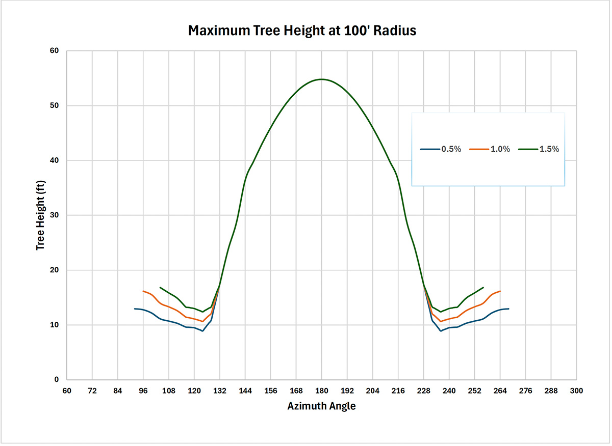
The sun azimuth angle for incremental combinations of solar declination angle (day of the year) and solar altitude angle (time of day relative to solar noon) for any given latitude is calculated. The graph shows the maximum tree height (defined as the maximum height a tree can be without casting a shadow on the solar array at any time during the year) at a radius of 100’ from the solar array with assumed maximum generation losses of 0.5%, 1.0% and 1.5% (based on relatively low intensity of sun light in early morning and late afternoon hours); the given latitude is 38° N.
Maximum tree heights are determined by a small range of dates centered around the winter solstice for the azimuth angles ranging from approximately 132° to 228° with 180° representing due south which occurs at Solar Noon. As the azimuth angle moves lower from 132° or higher from 228° the controlling day for each respective azimuth angle moves from the winter solstice to the summer solstice. Tree heights controlled by the winter solstice reflect days where solar altitude angles are not large enough to clear a tree taller than these limits. This shading from trees and buildings when the sun is at low angles doesn’t actually impact total production very much because the sun is at such a great angle to the plane of the solar array that there would be very little energy generation at that time period even if the trees or buildings were absent. Maximum tree heights for azimuth angles not associated with the winter solstice are dictated by the shallow solar altitude angles that occur in the early morning and late afternoon periods of the day.
A simple way to interpret/use this chart is to assume generation losses will not be exceeded if the surrounding tree/structure profile for the entire range of azimuth angles is below its relevant height limit. Areas where trees/structures are less than the maximum would reduce this annual loss estimate. Perhaps it goes without saying but height limits are proportional to the distance from the solar array.
Estimating Shade Loss
The profile of any object can be defined by a series of combinations of azimuth angles and solar altitude angles. The potential for shading begins when the angle between the object and the western end of the array matches the azimuth angle. As the day wears on, the azimuth angle works its way west to east along the array. Shading ends when the angle between the object and the eastern end of the array matches the azimuth angle.
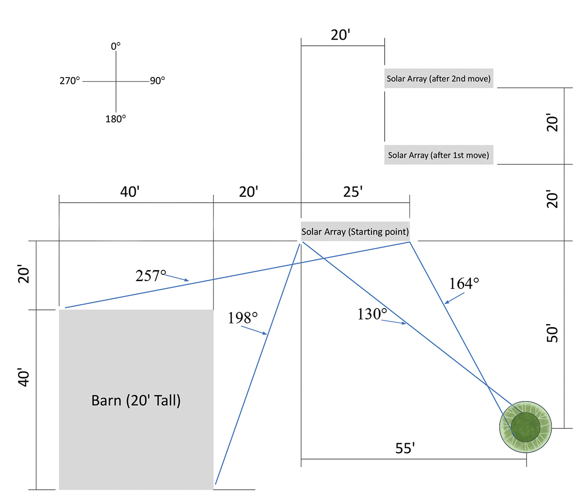
Trees located closer to due southwest and southeast have a much greater impact on potential generation losses. © Steve Moss
Within this range of azimuth angles, shading will only occur if the solar altitude angle is less than the vertical angle from the array to the top of the object (defined here as the minimum solar altitude angle). Although the minimum solar altitude angles within the range of azimuth angles can be easily calculated, the amount of the resulting lost generation is a much trickier value to calculate. This is because both the azimuth angle and solar altitude angle behave as a sine wave throughout the year. In addition, the intensity of sunlight is a function of the solar altitude angle; meaning the potential for generating electric power diminishes as the sun gets closer to the horizon.
Loss Due to Tree Shading
To determine the potential generation loss of a tree, the distance between the tree and the solar array and the azimuth angle are measured at site. The western end of the solar array is used for both measurements. The azimuth angle can be determined with the compass app on a smart phone by standing at the tree and pointing the phone toward the solar array. The tree height is also estimated (this can be done by someone holding a pole of a known length next to the tree and an observer visually estimating the tree height in terms of the number of pole lengths needed to match the tree’s height). There are, of course, more sophisticated methods of making these measurements.
The tree height, distance to tree, and azimuth angle are entered into a spreadsheet along with the dimensions of the solar array. Azimuth angles and distances to the tree are calculated for the various points along the object’s profiles. These distances are used to determine the minimum solar altitude angle for these various points.
Please refer to the plot sketch for a better understanding of a tree and barn location relative to the solar array. For illustration purposes, the tree’s profile is defined as two concentric cylinders; the first has a 6’ diameter and height equal to the estimated height of the tree; the second has a 12’ diameter and a height 5’ less than the height of the tree. These values can be varied and additional cylinders added, if needed.
In most cases, the shadow width will be less than the width of the solar array. Allowances are made for the fact that generation does still occur within the range of applicable azimuth angles.
In reality, the estimated width at the maximum tree height is an educated guess and will probably be less as the width dimension is taken closer to the top of the tree. In addition, no allowance for partial shading is made. It is also assumed the tree shadow is solid for the entire time it interferes with the solar array and does not factor in space between leaves, nor does it take into account the lack of leaves for non-evergreens during the winter months.
Loss Due to Structure Shade
In most cases, the dimensions of structures can be more accurately measured and shade losses more accurately estimated. Loss estimates are generated with the same method as for a tree.
Structure profiles are constant and not subject to seasonal variances; thus, fairly accurate loss estimates can be achieved and should be weighed accordingly when balancing between competing estimated losses associated with trees.
Optimizing Array Location
Site conditions may limit location flexibility, perhaps a range of trees to the immediate north of the proposed array location. There may also be limits based on aesthetic considerations. Perhaps, if the owner had no choice this could be acceptable, but if the owner could significantly reduce or even eliminate the loss by moving the array it should be considered. Although already well-established, the minimum distance between parallel arrays can also be calculated. This distance increases with latitude; variances in the topology of the area the arrays are being installed must also be considered.
Perhaps the most practical knowledge is the minimum distance required to avoid shading altogether. Another possibility may be determining if the array should be split into two (or more) rows if the site has competing shade producing or space limits to the east and west of the array. Alternatively, if there is a ridge of trees to the south of the array but not much to the east and west, a single solar array is likely the best configuration.
Trees and landscaping provide essential environmental benefits, but always consider how much shade they’ll throw as they mature. Deciduous trees (ones that drop leaves) on the east or west can block harsh summer sun while minimizing winter shading, but keep them far enough south from an array or rooftop system to prevent significant generation loss. Proper solar siting is essential for optimizing a solar array’s location and minimizing the impact to the nearby landscape—green is good!
Practical Tips for Homeowners
- Assess the site: Look at where trees and structures are located relative to the panels. Use a compass app on a smartphone to measure the direction from the tree to the panels.
- Estimate tree height: Hold a pole of known length next to the tree and estimate how many pole lengths it takes to match the tree’s height.
- Use tools and charts: There are online tools and charts that can help estimate how much shade a tree or structure will cast and how much energy might be lost.
- Consider alternatives: Sometimes, trimming branches or moving the array can reduce shade without removing trees. If removal is necessary, weigh the environmental benefits of solar energy against the loss of the tree.
- Consider Future Growth: Trees will grow, and new buildings may go up nearby. Factor this in—trim branches or plan for a little extra space.
- Advanced Panel Tech: If minor shade is unavoidable, panels with microinverters or power optimizers limit the “bottleneck” effect from a single shaded cell.
Example of a 50’ Tree
For illustration purposes a 50’ tall tree located 55’ east and 50’ south of the western end of the solar array is assumed. The range of affected azimuth angles is 130° to 164° for the 6’ diameter portion and 128° to 167° for the 12’ diameter portion. Minimum solar altitude angle ranges from 34° to 41° for the 6’ diameter portion and 31° to 38° for the 12’ diameter portion. The 12’ diameter minimum solar altitude angles are lower because the assumed height is 5’ lower than for the 6’ diameter portion.
This tree will provide an estimated 170 hours of shade and reduce annual generation by about 2.6%. General loss estimates for alternate locations will be discussed in the context of minimizing the total of this tree and a nearby barn later in this article. Note: the 170 hours represent about 3.9% of total hours of sunlight; the difference between this and the loss estimate reflects the lower intensity levels associated with some of the shaded area.
Example: A 20’ tall barn with its northern wall located 20’ south with its eastern wall located 20’ west of the western end of the solar array. All four sides are 40’ long. For simplicity, the orientation of this barn is assumed to be true to the N/E axis. With this barn’s assumed dimensions and location, the associated azimuth angle range is 198° to 257° with the minimum solar altitude angle ranging from 13° to 18°.
This barn would provide an estimated 240 hours of shade and reduce annual generation by about 3.1%. As was the case for the tree example, the estimated loss value is much less than the 5.5% of annual hours where this barn is shading the solar array due to the lower intensity of much of the area affected.
The combined annual generation loss of the tree and barn is about 5.7%. The typical capacity of a 25’-wide array is about 6 kw which would be expected to produce about 8400 kwh’s per year. Applying this loss estimate to the total generation yields annual cost estimates of about $48 based on a value of $0.10 per kwh. Assuming the discount rate equals the inflation rate of electricity, the NPV of this annual cost comes to about $960 based on a 20-year life of the array.
If the array can be moved 20’ to the east and 20’ to the north, estimated generating losses of the barn are reduced about 85% to 0.5% annually while losses tied to the tree are reduced more modestly by about 10% to 2.3%. The losses tied to the tree are reduced by the array shift north but this is almost entirely neutralized by the move east.
Starting at this secondary location and moving the array north by another 20’, losses to the barn and the tree are each reduced to about 0.2%. At this point, the benefit of moving further north may need to be compared to any additional cost or detriment that may be incurred.
About the Authors
Steve Moss received a BS in Mechanical Engineering from the University of Missouri – Rolla (now MS&T) in 1976 and retired from Nooter/Eriksen as a Senior VP in 2015 after 39 years of service. Mr. Moss is a past president of the Academy of Mechanical and Aerospace Engineers at MS&T and is currently a trustee at Ranken Technical College, located in
St. Louis, MO.
Carly Rixham is the Executive Director for American Solar Energy Society (ASES). She is the Publisher of Solar Today magazine. Her research is in the intersection of solar energy and landscape architecture. She received her Masters in Ecology and Evolutionary Biology at University of Colorado Boulder. Rixham was a microbiologist at BioVantage Resources, culturing algae for bio-remediation of nutrients in wastewater. She enjoys travel, art, mountain sports, and nature.